| < Prev | Home | Index | P1 | P2 | P3 | P4 | Next > | ||
| A01 | A02 | A03 | A04 | A05 | A06 | A07 | A08 | A09 | A10 |
| A11 | A12 | A13 | A14 | A15 | A16 | A17 | A18 | A19 | A20 |
| A21 | A22 | A23 | A24 | A25 | A26 | A27 | A28 | A29 | A30 |
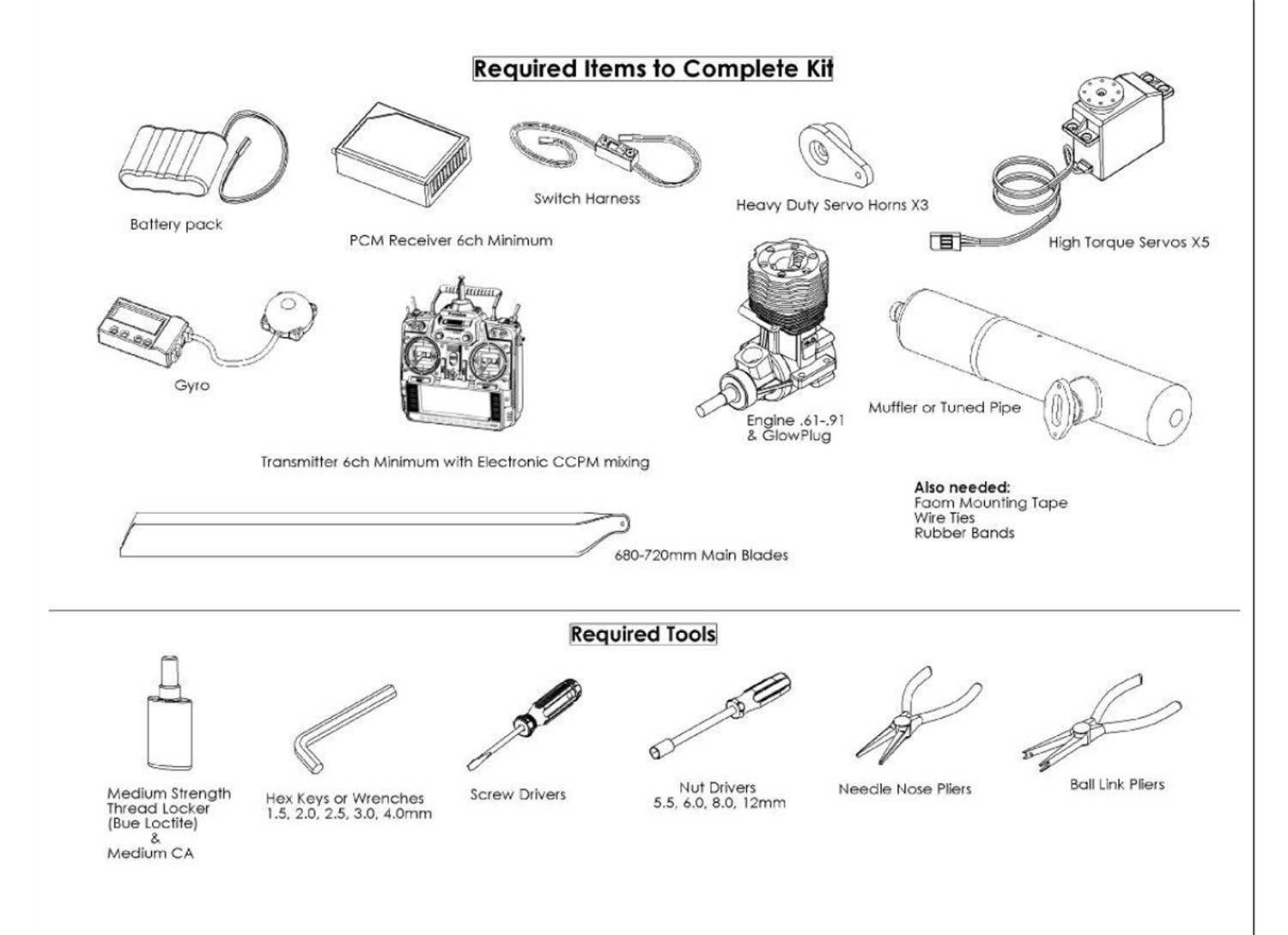
Be sure to use a heavy duty switch harness.
Early versions of the SB16FH had too short of a header. Check to see that there is sufficient clearance or it will melt the side of the fuel tank (110-330). To mount it, remove the pipe from the mounting plate. Make sure the short side of the plate is on the front side (you'll probably have to turn it 180 degrees). Add a small amount of grease to help push the pipe back on. This should be done near the end of the build. I had troubles with the screws eventually coming loose. Use red loctite on all muffler bolts due to the heat involved.
Other recommended items include: remote glow adapter, wire wrap, velcro to secure gyro sensor, packing foam and velcro strap to secure the electronics, header tank, fuel filter, fuel tubing, check valve (for YS engines), governor, voltage monitor, exhaust diverter, MA wire clips (to secure gyro sensor wire).
Other recommended tools include: pitch gauge, dial indicator, paddle alignment tool, dremel, glow wrench.
For dealing with larger sized ball links, Todd just uses some needle nose pliers. Twist the link and use the pliers at an angle to pop them off. Pinch them together to pop them on.
Zip tie the exhaust diverter to the muffler.
Use the following values for the GY611: delay DIIA/B = 10/10 DIDA/B = 50/50, mode=3d, limitAB=120/120.
Check the operation of the gyro as follows: twisting the gyro sensor to the left should move the tail control rod forward.
Cut a slot in the velcro strap to accommodate the wire to the amplifier, or turn the sensor 90 degrees.
Tape the crystal into the receiver to prevent it from coming out.
Use soft mounting tape for the gyro and governor (3M 4408 1/8" double-sided foam tape) available at uline.com.